
Reactance and Impedance
Reactance and Impedance: Overview
This topic covers concepts, such as, Pure Inductance AC Circuit,Phase Difference in Voltage and Current in Pure Inductance,Graph of Voltage and Current Versus ωt in Pure Inductive Circuit etc.
Important Questions on Reactance and Impedance
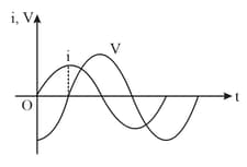
An a.c. source, of voltage , is applied across a series LCR circuit. Which of the following is the phasor diagram for the circuit when capacitative impedance exceeds the inductive impedance?
An a.c. voltage of , is connected across resistor and inductor in series. What is the impedance of the circuit?
In a series circuit, the voltages across an inductor, a capacitor, and a resistor are , and respectively. The phase difference between the applied voltage and the current in the circuit is
When an inductor and a resistor in series are connected across a , supply a current of flows in the circuit. The current differs in phase from applied voltage by radian. The value of is
In a series LCR circuit, the voltage across an inductor, capacitor and resistor are , and respectively. What is the phase difference between the applied voltage and the current in the circuit?
An inductor of inductance is connected to a a.c. source. Let the inductive reactance in the circuit be . If a dc source replaces the ac source in the circuit, then the inductive reactance in the circuit is. , respectively are:
An ac source is connected to a capacitor . Due to decrease in its operating frequency:
In a series circuit, the inductance is , capacitance is and resistance is . The frequency at which resonance occurs is:
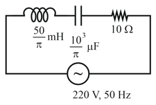
The net impedance of circuit (as shown in figure) will be:
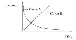
As per the given graph, choose the correct representation for curve and curve
{Where Reactance of pure capacitive circuit connected with A.C. source
Reactance of pure inductive circuit connected with A.C. source
Impedance of pure resistive circuit connected with A.C. source
Impedance of the series circuit }
Given below are two statements:
Statement I: Maximum power is dissipated in a circuit containing an inductor, a capacitor and a resistor connected in series with an source, when resonance occurs.
Statement II: Maximum power is dissipated in a circuit containing pure resistor due to zero phase difference between current and voltage.
In the light of the above statements, choose the correct answer from the options given below:
A capacitor of capacitance is connected to an alternating source of emf given by . The maximum value of current in the circuit is approximately equal to:
The variation of impedance with angular frequency for two electrical elements is shown in the graph given.
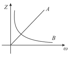
If and are inductive reactance, capacitive reactance and resistance respectively, then
In the givengraph of an circuit, the circuit may be
A series RC circuit with resistance capacitance is connected to A.C. supply of , . Find the current in the circuit and potential difference across the resistor and the capacitor.
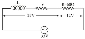
Coil is connected to an ac source through a resistance in series. The source voltage, voltage across the coil and voltage across the resistance are found to be , and respectively. Therefore, the resistance of the coil is
Find the voltage across the various elements, i.e. resistance, capacitance and inductance which are in series and having values , and , respectively. Given emf is .
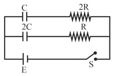
In the circuit shown in the figure switch is closed at time . Select the correct statement
The phase difference between input between input and output voltage dor the following circuit in (i) and (ii) will be
(i)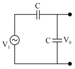 (ii)
(ii)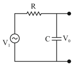
Given below are two statements:
Statement-I: In an ac circuit, the current through a capacitor leads the voltage across it.
Statement-II: In a.c. circuits containing pure capacitance only, the phase difference between the current and the voltage is In the light of the above statements, choose the most appropriate answer from the options given below:


